This page is not meant to be all inclusive or in any way complete or extremely detailed.
For more information on these cameras, please refer to the links section at the bottom of the page.
For the purpose of this web page, I will exclude the cameras carried in the Command Module and in the J-Series Service Module’s Scientific Instrument Module (SIM) bay and focus primarily on the still and video cameras used on the lunar surface.
Note: As is the case with a large part of My Little Space Museum, much of the information and images on this page were obtained from the Apollo Lunar Surface Journal, and Kipp Teague’s incredible Project Apollo Image Archive.
Still Cameras:
Hasselblad 70mm EDC
Maurer 16mm Data Acquisition Camera
Video Cameras:
Apollo 11: Westinghouse Apollo Lunar Television Camera
Apollos 12-14: Westinghouse Lunar Color Camera
Apollo 15-17: RCA J-Series GCTA
Miscellaneous:
Apollo Lunar Surface Close-up Camera
Apollo 14: Lunar Geological Exploration Camera (Not Flown)
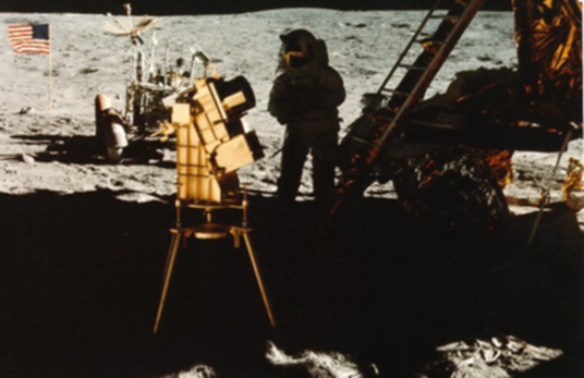
Apollo 16: Far Ultraviolet Camera/Spectrograph (FUVC)
Related Links
The Hasselblad 70mm EDC
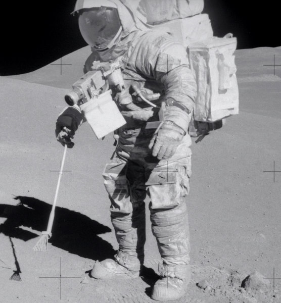
By far the most famous of all Apollo cameras, and perhaps the most important as well, was the Hasselblad EDC, which was adapted from a camera of the same company, designated the Hasselblad 500 EL. Nicknamed “Hassies”, these 70mm cameras were used by the astronauts on the lunar surface for still photography, and, as such, took almost all of the photographic images brought back from the lunar surface.
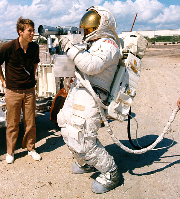
Because these camera systems had no viewfinder, and were worn on the chest during lunar EVAs, a lot of practice was needed to master their use. To that end, the astronauts were issued cameras to take home and practice with.
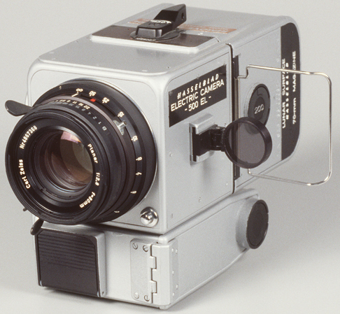
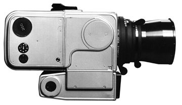
Left: The “civilian” version of the Hasselblad camera used on the moon, the 500 EL.
The square black object under the lens is the shutter release button.
Right: The lunar version of the camera, without the handle and RCU mount.
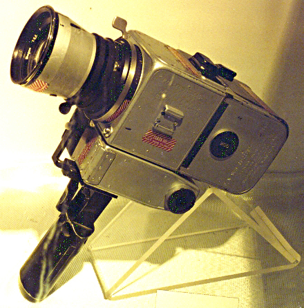
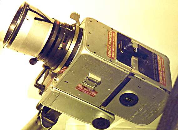
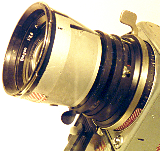
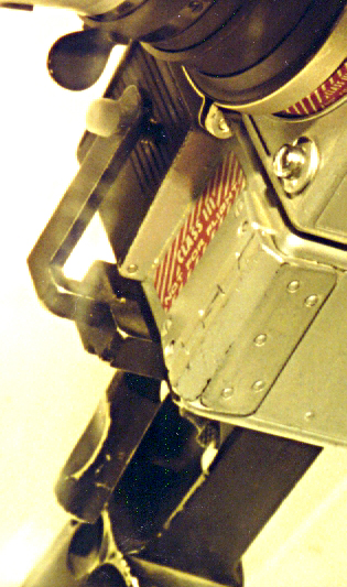
My own photos of the Hassie, taken at the Neil Armstrong Museum in Ohio.
Note the handle that has been attached for lunar use, and the trigger mechanism.
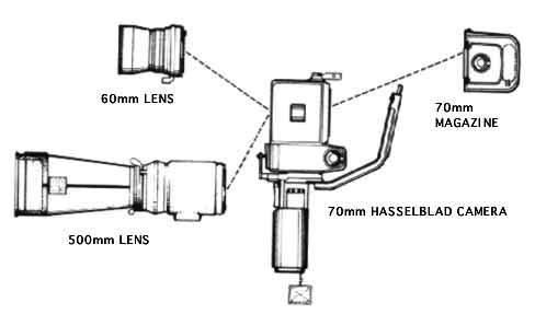
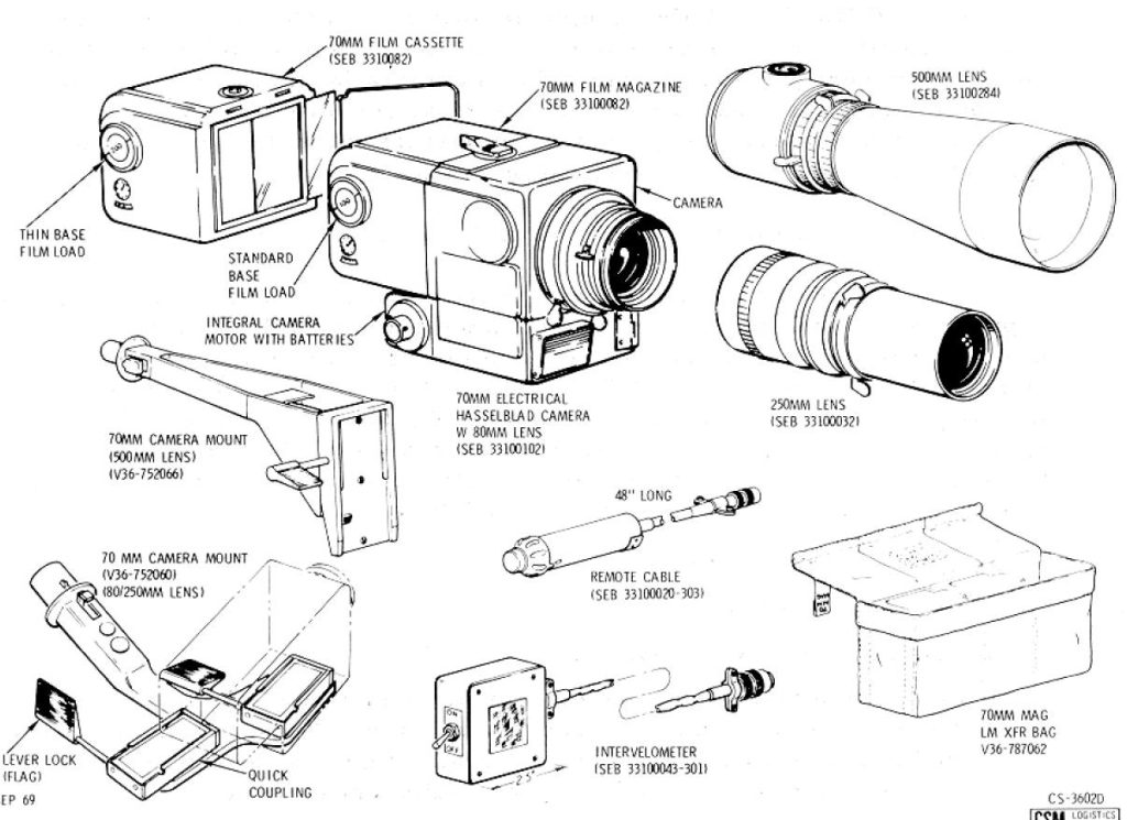
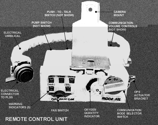
NASA diagrams. The one on the right shows several features
that were used only onboard the Command Module.
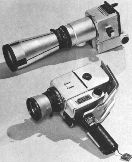
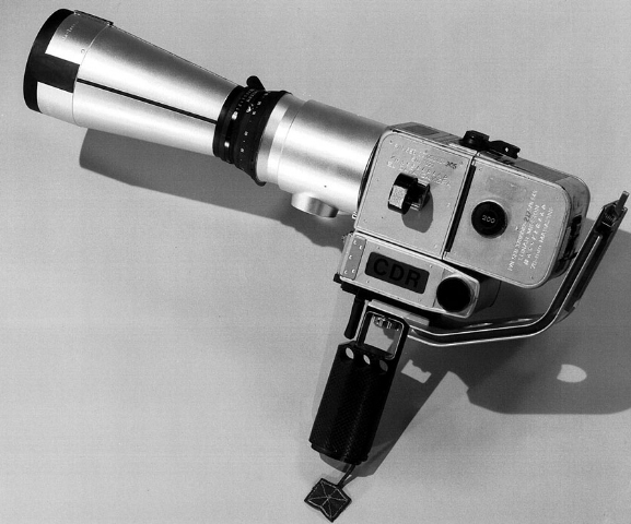
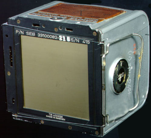
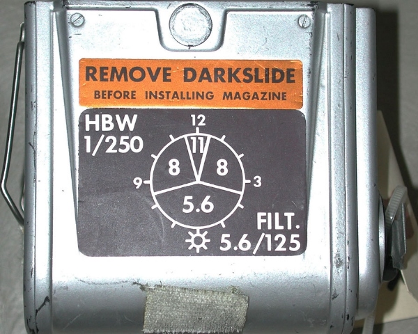
Film magazine & camera top decals
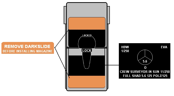
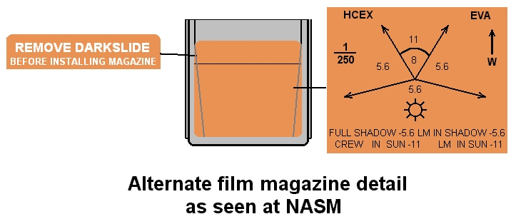
The Maurer 16mm Data Acquisition Camera
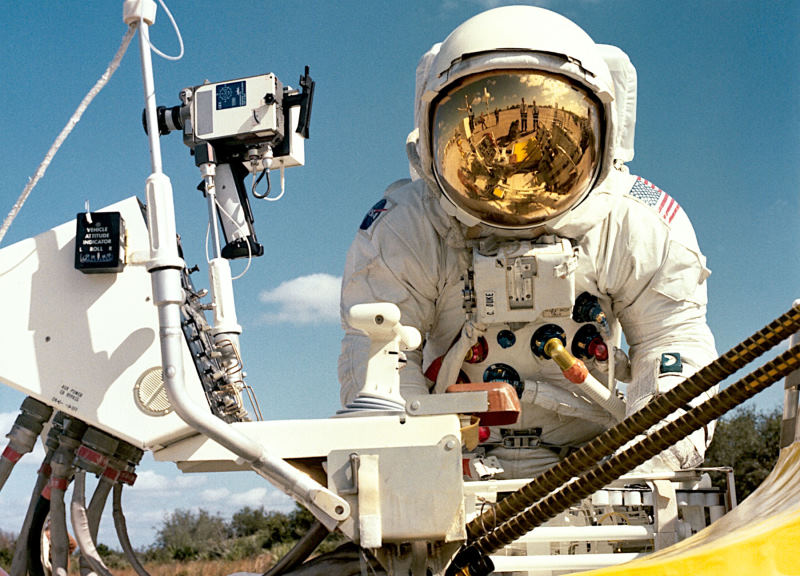
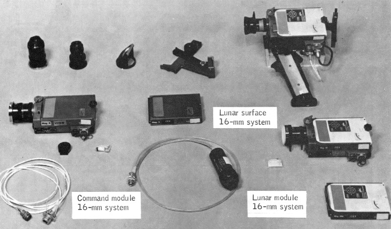
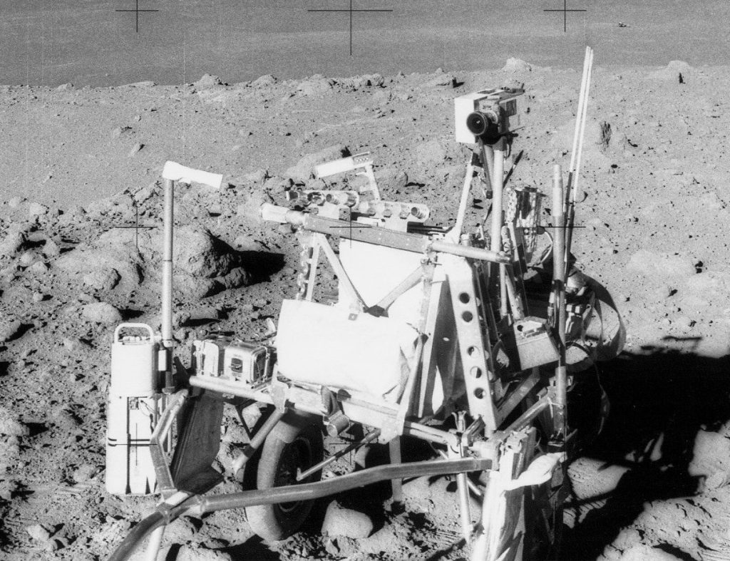
The 16mm Maurer Data Acquisition Camera (usually called “the DAC”, pronounced simply “dak”) is best known for the movies it was used to take through the Lunar Module Pilot’s (LMP’s) window during the approach and landing of the LM. Also, all of the movie footage taken on the lunar surface (not to be confused with the video downlink) was done with the DAC. On Apollo 11, it was also used to take stop motion photography out the LMP’s window of almost the entire EVA at the setting of 1 frame per second (fps). On 12, it was mounted on the Lunar Hand Tool Carrier, on 14 it was mounted on the MET, and on the J-Series missions it was mounted on the Lunar Roving Vehicle (LRV). On 2 of the J-Series missions, 15 & 16, it was primarily used to document the geology along the LRV route, set at 1 fps.
A slightly different version of this system was used on board the CSM to take movies of such things as docking operations, etc.
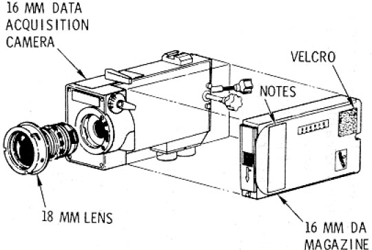
Simple diagram showing main elements of the system.
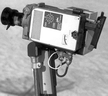
Beauty shot of the DAC from a training photo.
Westinghouse Apollo Lunar Television Camera
Used on the lunar surface on Apollo 11 only.
Brought as backup camera on Apollo’s 13 & 14
Few people who lived during the time of Apollo will ever forget where they were when they watched Neil A. Armstrong make his “One small step” into the history books on July 20, 1969. The fuzzy, gray images beamed back from the lunar surface for 2 hours that night allowed all of us to share in the wonder of that historic event.
The machine that was used to do this was named simply the Apollo Lunar Televsion Camera. Built by Westinghouse, it was a simple system which measured 11″ x 6″ x 3″, weighed 7.25 pounds, and used 6.25 watts of power. It was capable of operating at 10 or 0.65 frames per second, depending on light level, and it had 4 interchangeable lenses.
The camera was mounted inside the Modularized Equipment Stowage Assembly (MESA) in Quad 4 of the Lunar Module (LM) Descent Stage. This gave the capability of broadcasting the first steps of the astronauts as they climbed down the ladder of the LM at the start of the first EVA. The astronauts would then
detach the camera from it’s mount in the MESA, mount the camera on a tripod, and carry it away from the LM to show the progress of the EVA.
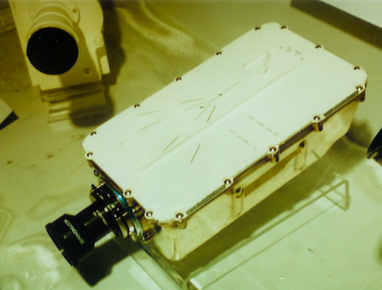
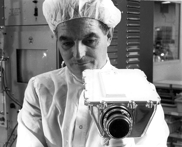
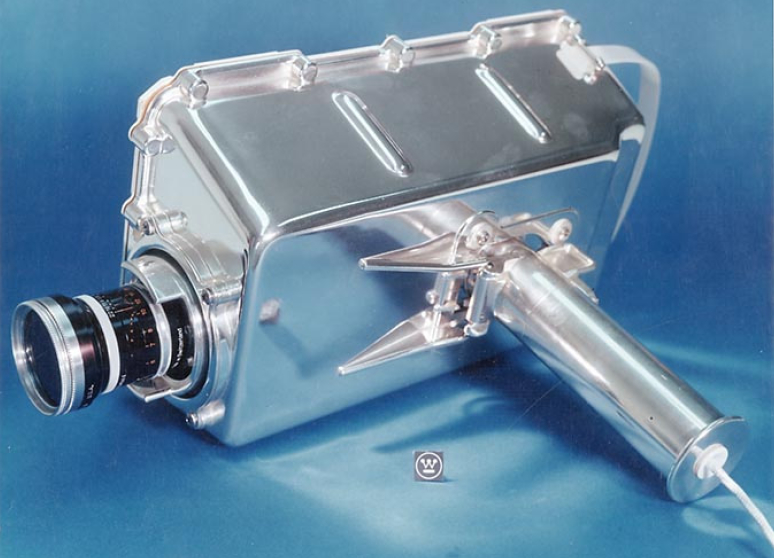
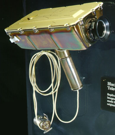
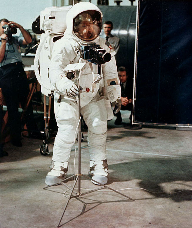
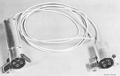
Above – photos of the camera on earth.
Right photo is of the electrical cable that connected the camera to the LM.
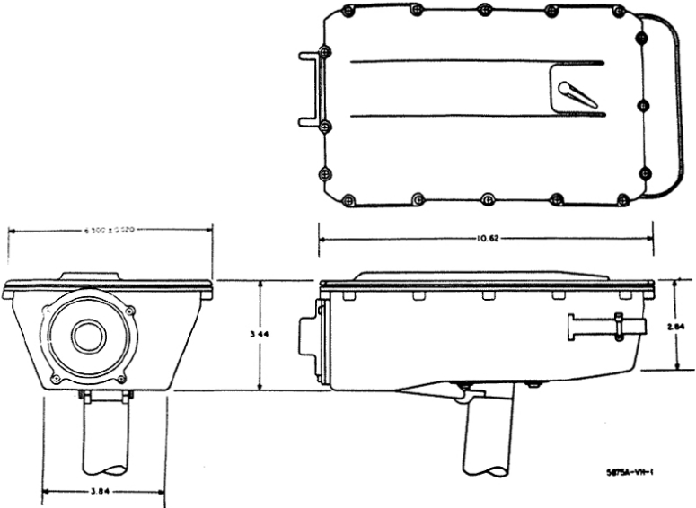
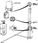
Two simple diagrams. The one on the left has dimensions.
Westinghouse Lunar Color Camera
Used on Apollo’s 12 & 14
The camera was mounted inside the Modularized Equipment Stowage Assembly (MESA) in Quad 4 of the Lunar Module (LM) Descent Stage. This gave the capability of broadcasting the first steps of the astronauts as they climbed down the ladder of the LM at the start of the first EVA.
The astronauts would then detach the camera from it’s mount in the MESA, mount the camera on a tripod,
and carry it away from the LM to show the progress of the EVA.
This system was the same TV camera used on previous missions inside the CSM, with a few minor modifications to adapt it to the lunar environment. It was called the Field Sequential Camera by Westinghouse.
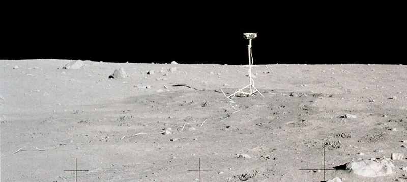
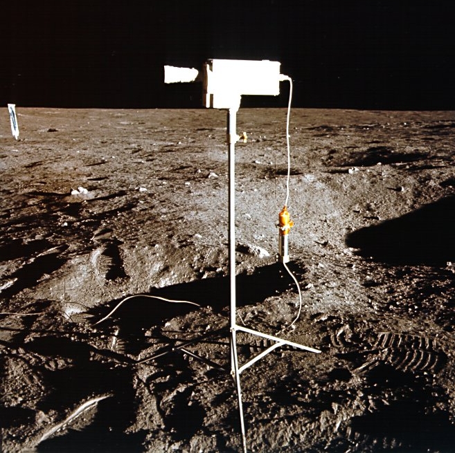
Unfortunately, during the early moments of the first Apollo 12 EVA, which marked the camera’s debut on the moon, astronaut Alan Bean inadvertantly pointed the camera at the unfiltered sun while preparing to mount it on the tripod. This action caused an overload in the secondary vidicon tube, rendering the camera useless for the remainder of the mission. It worked reasonably well on Apollo 14, although there were a few problems encountered with the image brightness and contrast.
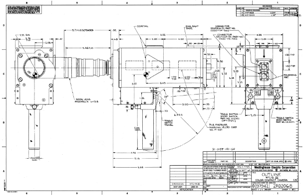
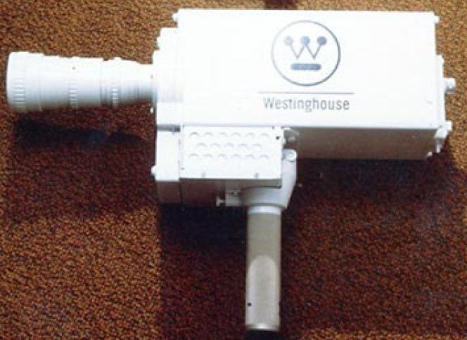
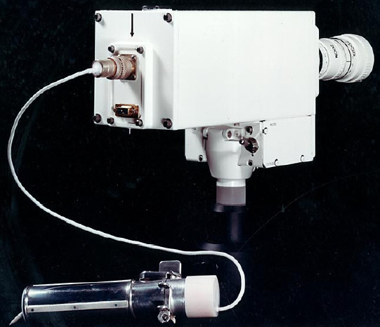
Left & Center: These are about the only decent color photos I’ve been able to find of this camera pre-flight
Right – Apollo 12 camera at the Ocean of Storms after it’s fatal malfunction
RCA J-Series
Ground-Commanded Television Assembly (GCTA)
Used on Apollo’s 15, 16, & 17
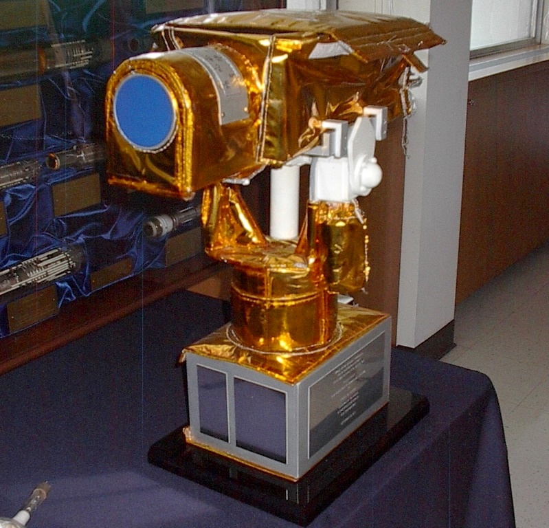
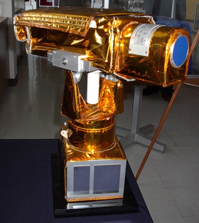
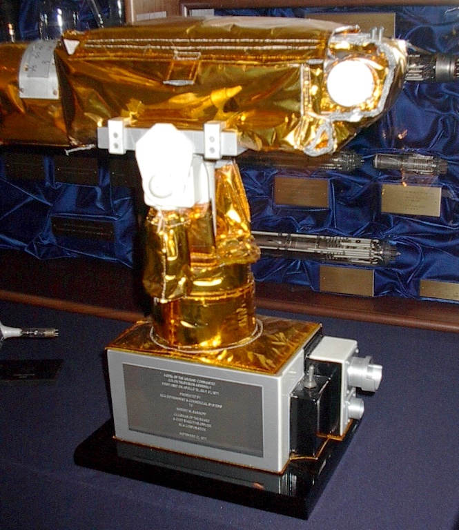
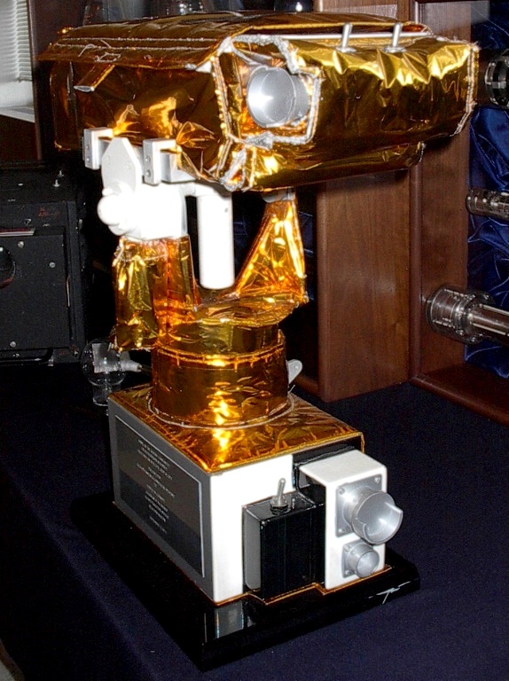
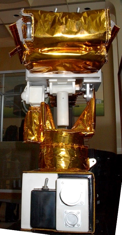
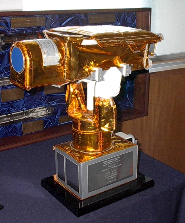
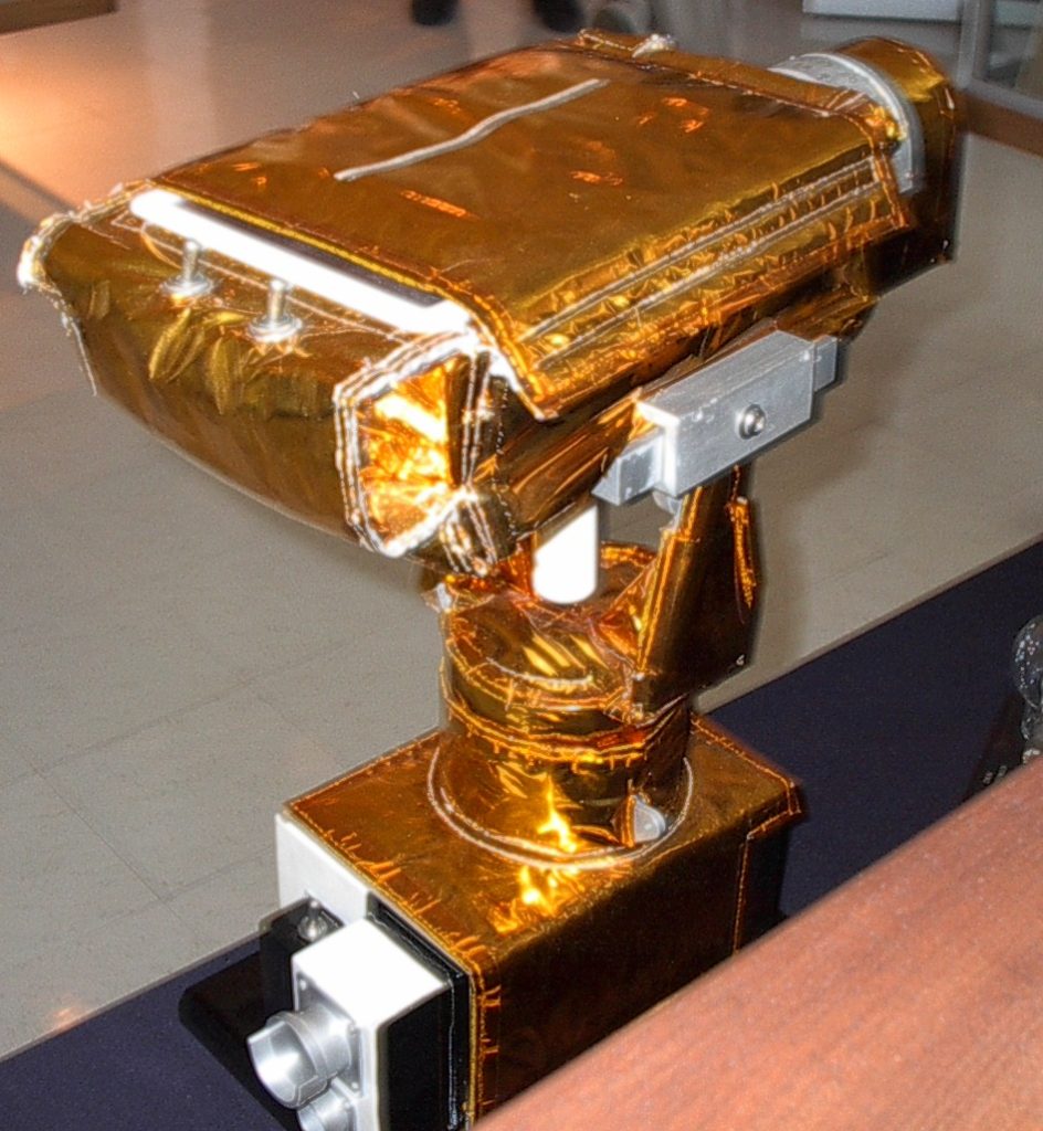
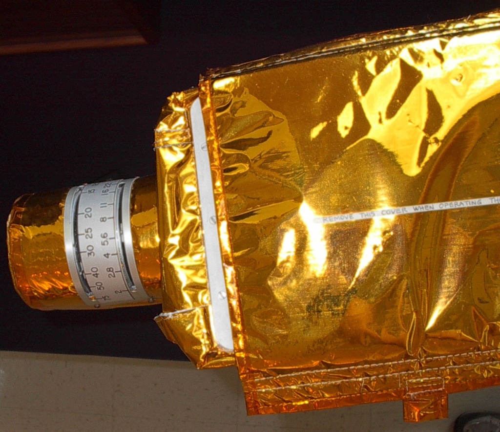
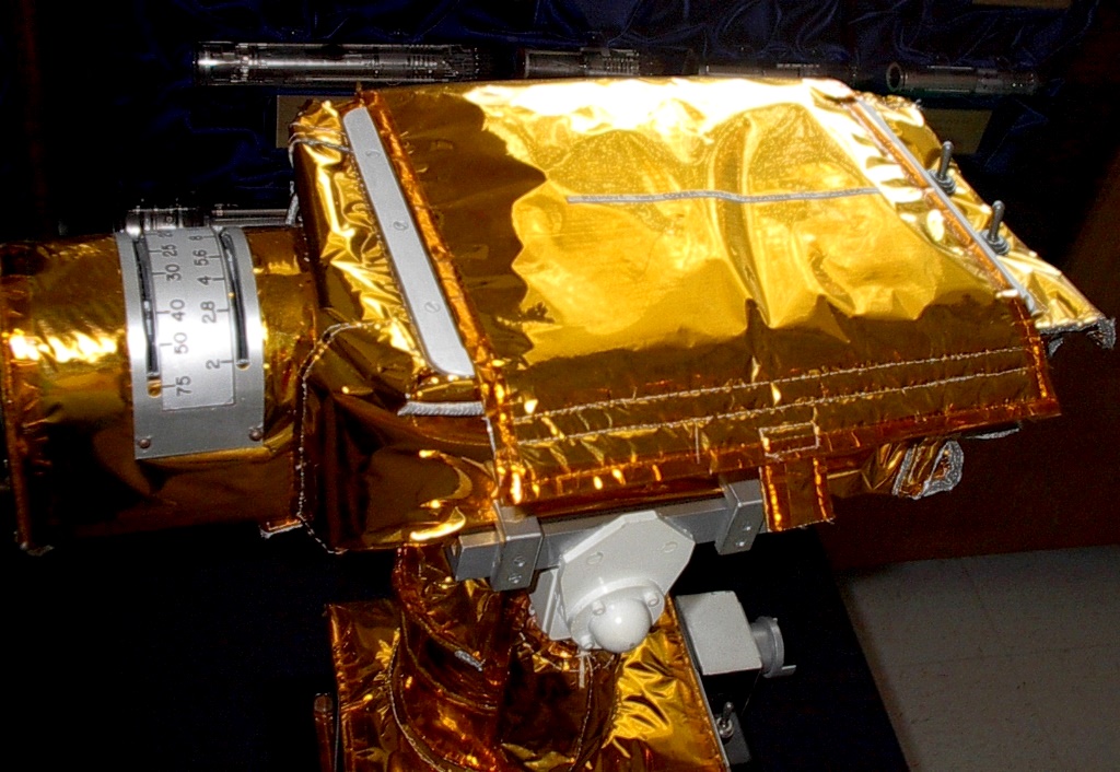
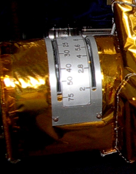
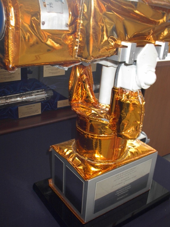
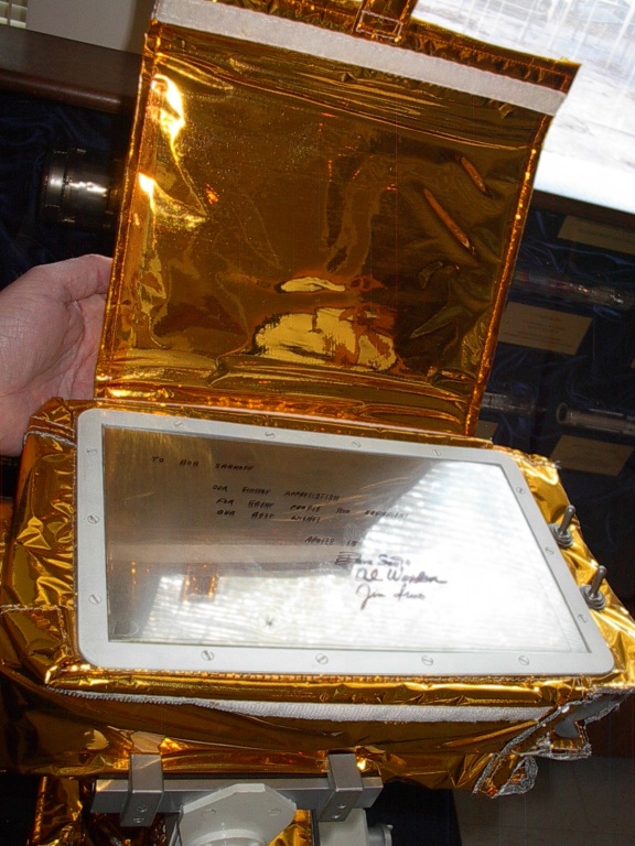
Above: A fabulous set of photos of the GCTA on display at The David Sarnoff Library,
graciously donated by Mr. Frank O’Brien
An MLSM Exclusive
Note last photo shows where Apollo 15 crew signed this museum piece.
This advanced system flew aboard the J-Series lunar missions on Apollos 15, 16, & 17. It gave unprecedented quality in the color video transmitted from the moon. But, alas, few people watched as America had by this time lost interest in watching men on the moon.
The system consisted of two major components: the Color Televsion Camera (CTV), and the Television Control Unit (TCU). This system was connected directly to the Lunar Communications Relay Unit (LCRU) when mounted on the Lunar Roving Vehicle (LRV), and the TV signal was sent from the LCRU to earth via the High Gain Antenna (HGA) mounted on the LRV.
As with all previous missions, the system was mounted inside the Modularized Equipment Stowage Assembly (MESA) in Quad 4 of the Lunar Module (LM) Descent Stage. This gave the capability of broadcasting the first steps of the astronauts as they climbed down the ladder of the LM at the start of the first EVA. The astronauts would then
detach the camera from it’s mount in the MESA, mount the camera on a tripod, and carry it away from the LM to show the progress of the EVA. (The crews of Apollo’s 16 & 17 chose to wait until it was setup on the LRV before activating the TV, in order to save time, no doubt). What made this camera truly unique was that, once the LRV was fully deployed, it was then mounted on the LRV and controlled by commands from the ground to tilt, pan, and zoom in and out.
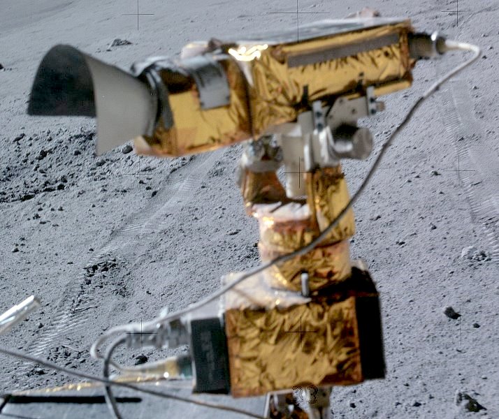
Above Left – Apollo 16 photo of the GCTA/TCU. Note the white sunshade over the lens,
which was added after Apollo 15, and the manual lens adjustment levers on top of the lens
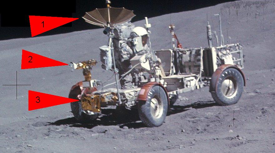
Right – Another Apollo 16 photo, showing all 3 main elements of the LRV TV system:
1. High gain antenna (HGA)
2. GCTA/TCU
3. Lunar Communications Relay Unit (LCRU)
The signal from the camera was routed through the LCRU, processed,
then transmitted to Houston through the HGA
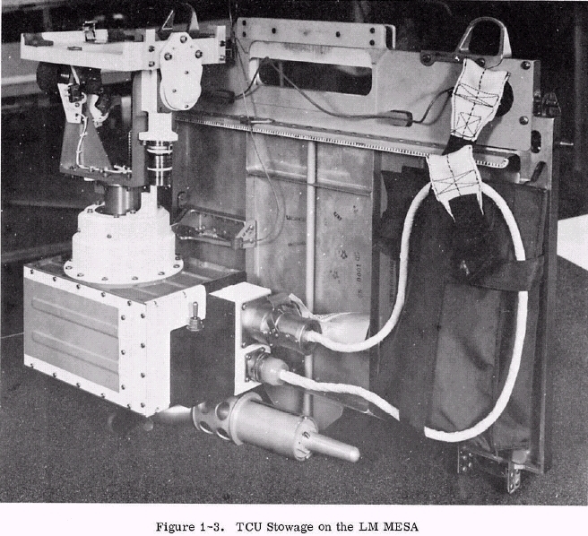
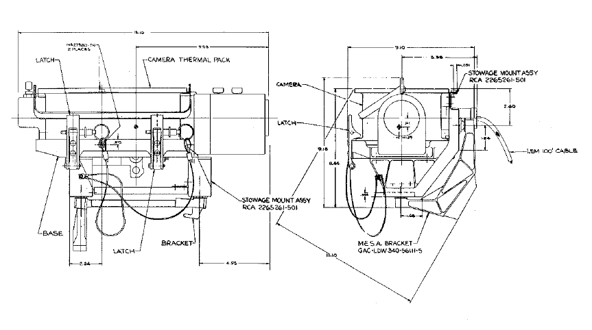
MESA pallet stowage of the TCU, photo and diagram
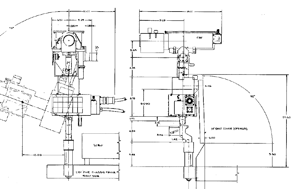
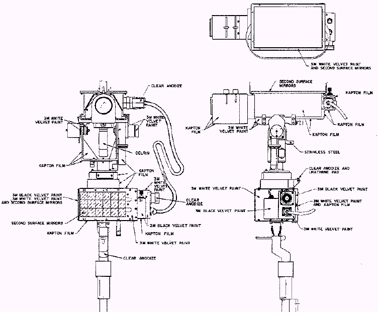
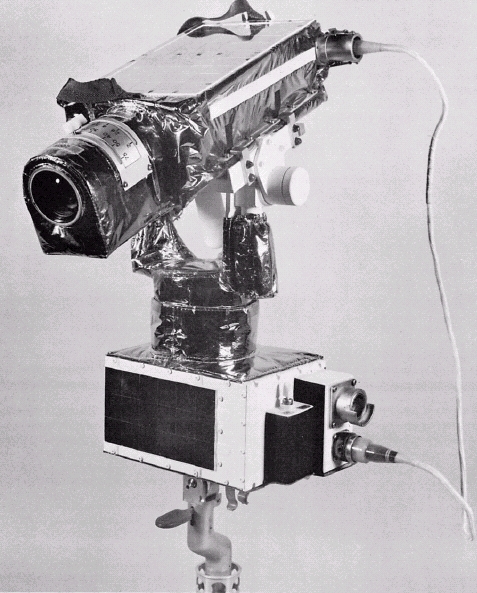
Above left and left center – 2 great diagrams of the GCTA/TCU system, with dimensions
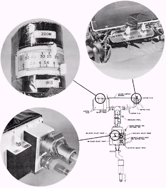
Center – controls on the GCTA, including the lens control levers
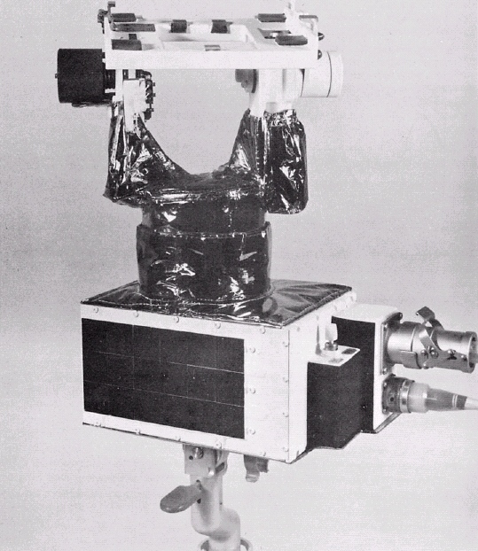
Right center – TCU alone
Right – TCU/GCTA combination – note absence of sunshade, as it was used on Apollo 15
Apollo Lunar Surface Close-up Camera
For information on this system, see my ALSEP page on the subject.
Apollo 14 Lunar Geological Exploration Camera (Not Flown)
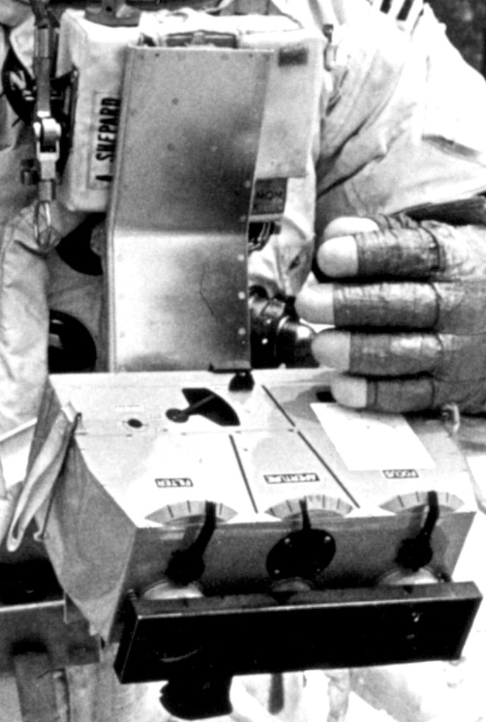
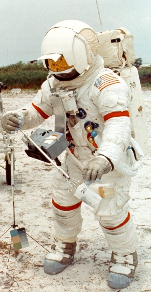
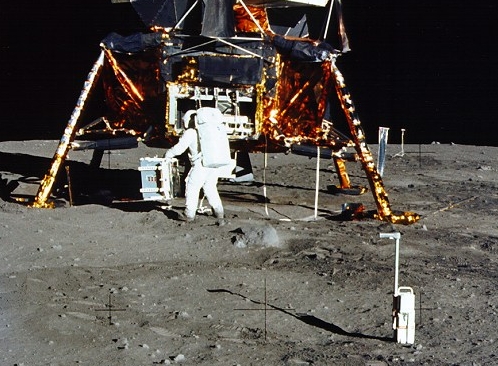
Very little has been written about this system. It is known that it was originally part of a Lunar Geological Staff conceived by Gene Shoemaker. According to the Apollo Lunar Surface Journal, it was subcontracted to a small company that was unable to handle the complexities of the assignment, and was subsequently cancelled.
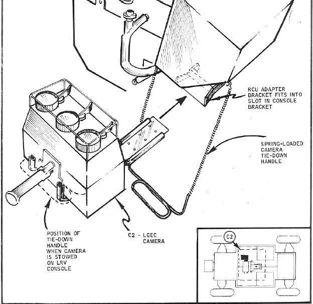
Quite by accident, I managed to find a diagram showing the camera, in a GE Apollo Systems Publication about the Lunar Roving Vehicle (LRV). The document is titled “Lunar Roving Vehicle Crew Equipment Stowage Methods and Location”, dated June 5, 1970. This diagram shows that it would have been mounted under the main console of the LRV.
Apollo 16 Far Ultraviolet Camera/Spectograph (FUVC)
For information on this system, see my ALSEP page on the subject.
